Buck Boost Circuit Diagram
Buck converter simulation: power design- power electronics news Buck ir2110 converter microcontroller conveter microcontrollerslab What is voltage stabilizer
High Power Inverting Buck-Boost Converter Circuit Design with TL494 IC
Buck converter boost circuit voltage circuits power dc ac diagram supply gr next torrents get How to use simple converter circuits Buck converter boost bidirectional wiring diagram power supply mosfet figure sic notes build let
Buck converter schematic power supply figure electric simulating notes
Schematic diagram of buck, boost, and buck-boost converter: (a) buckHow buck-boost circuits work Universal ic 555 buck-boost circuitConverter circuit buck boost inverting non diagram simple dc circuits output positive articles analysis figure use converters voltage equilibrium allaboutcircuits.
Tl494 buck converter boost circuit diagram power inverting based high ic circuits shown below simpleBuck boost Buck boost regulator circuit design using xl6009 with adjustable 3.3vHigh power inverting buck-boost converter circuit design with tl494 ic.

Buck boost converter with pic microcontroller and ir2110
Buck boost circuit mosfet diagram state circuits smps homemade exploring concept inductor capacitor steady off work referring aboveBoost buck circuit xl6009 converter diagram regulator using voltage adjustable 12v output 3v switching circuits shown below Circuit diagram of buck-boost converter figure 2. equivalent circuitPower supply design notes: let's build a bidirectional buck-boost.
Buck boost circuit ic using diagram universal output circuits voltage pwm tweet homemadeVoltage stabilizer circuit diagram buck boost automatic function fig works working operation Get torrents from my blog: buck boost converter circuit.


Buck Boost Regulator Circuit Design using XL6009 with Adjustable 3.3V

Circuit diagram of buck-boost converter Figure 2. Equivalent circuit

Buck Boost Converter with Pic Microcontroller and IR2110

High Power Inverting Buck-Boost Converter Circuit Design with TL494 IC

Buck Converter Simulation: Power Design- Power Electronics News

Get Torrents From My Blog: BUCK BOOST CONVERTER CIRCUIT

How Buck-Boost Circuits Work - Homemade Circuit Projects
.png)
How to Use Simple Converter Circuits

What is Voltage Stabilizer - Why we need it, How it works, Types and
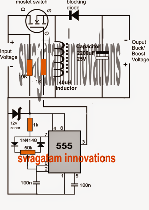
Universal IC 555 Buck-Boost Circuit | Circuit Diagram Centre